
— —
Punching Marking Process Explained: Suitable Materials, Thickness, and Limits
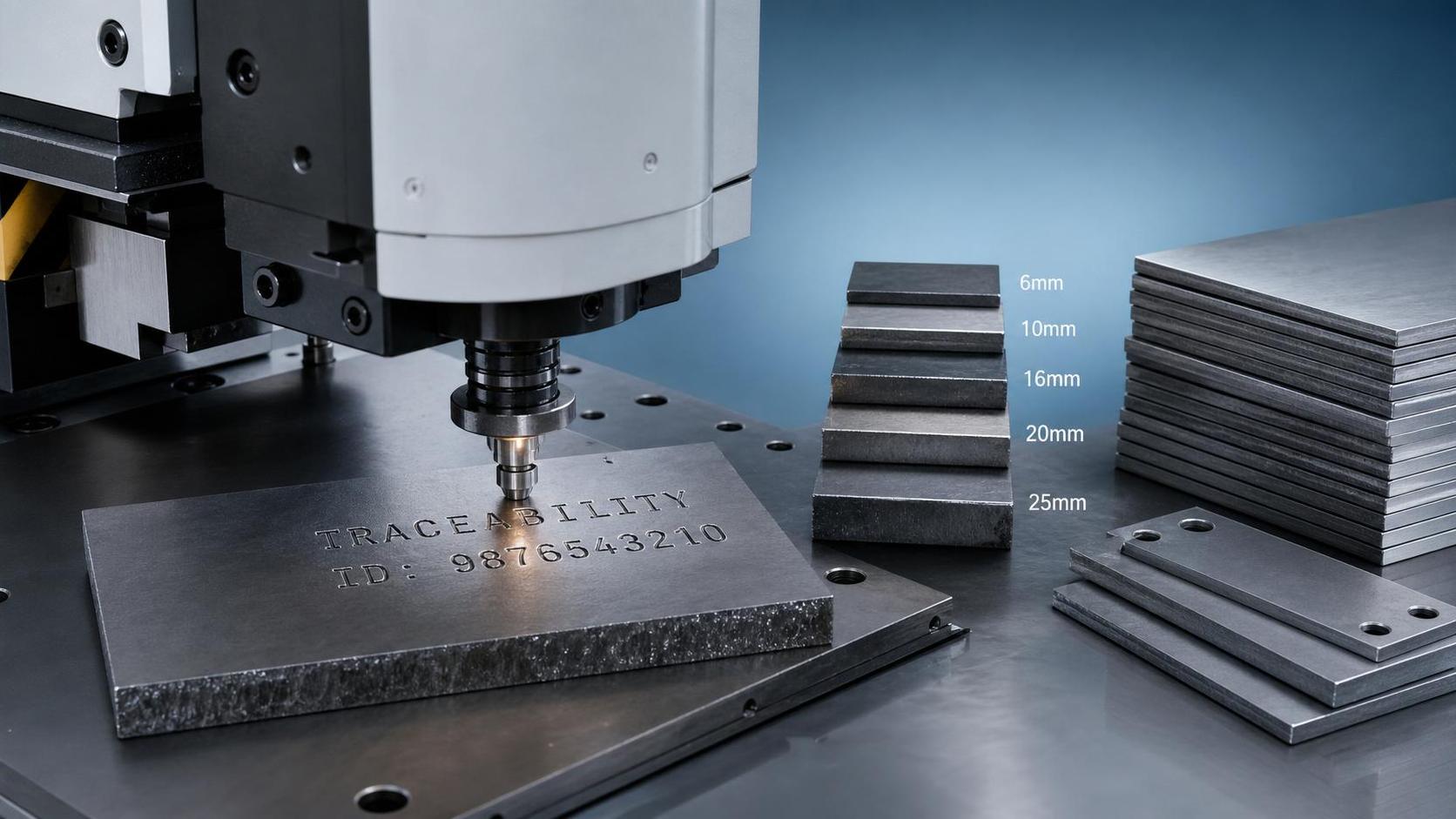
Punching Marking Process Explained: Suitable Materials, Thickness, and Limits
For quality control and safety management teams, understanding the punching marking process is essential to ensuring traceability, readability, and material integrity.
This guide explains how punching marking performs across different metals, suitable thickness ranges, and practical limits.
The goal is simple: help you judge whether this method fits production, compliance, and inspection needs in modern fabrication.
What Punching Marking Actually Does
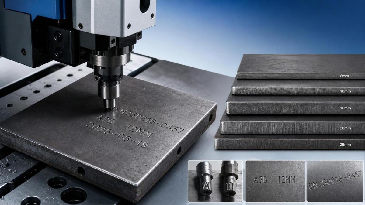
Punching marking creates letters, numbers, or symbols by mechanically indenting the metal surface with force.
Unlike ink, labels, or paint, the mark becomes part of the material itself.
That is why punching marking remains common in traceability systems for plates, profiles, and structural components.
In practical terms, the process is valued for permanence, low running cost, and simple downstream identification.
However, punching marking is not universal. Material hardness, thickness, surface condition, and code depth all affect the result.
More importantly, a readable mark is not always a safe mark.
If the indentation is too deep, it can create stress concentration or cosmetic rejection.
So the process must be assessed as both an identification method and a material intervention.
Suitable Materials for Punching Marking
The best materials for punching marking are metals that accept controlled deformation without cracking or severe springback.
Low-carbon steel is usually the most suitable option.
It allows clean indentation, stable readability, and predictable mark depth during routine production.
Stainless steel can also be marked, but the result depends heavily on grade and hardness.
Austenitic grades often need higher force and tighter tool maintenance.
Aluminum is generally easy to indent, yet soft surfaces can distort, smear, or lose edge clarity.
Copper is similar. It marks easily, but its ductility may reduce sharp character definition.
Materials with scale, coatings, or rough surfaces create another challenge.
The punch may break through the surface layer unevenly, making the code harder to read.
For galvanized or painted parts, post-process appearance and corrosion concerns should be reviewed before approval.
- Best fit: mild steel, carbon steel, normalized plate.
- Conditionally suitable: stainless steel, aluminum, copper.
- Poor fit: brittle alloys, hardened steel, finish-critical decorative surfaces.
Thickness Range: Where Punching Marking Works Best
Thickness is one of the most important limits in punching marking.
Very thin sheets may deform, warp, or show backside witness marks.
Very thick sections may accept the mark, but readability can drop if the punch stroke is not adjusted properly.
In many fabrication shops, punching marking performs best on medium-thickness carbon steel plates and profiles.
A useful rule is to verify four things together: thickness, hardness, support condition, and required mark depth.
This is not a universal standard, but it reflects common shop-floor behavior.
Actual acceptance should still come from procedure qualification, internal quality rules, and customer specifications.
Key Limits You Should Not Ignore
The biggest mistake is treating punching marking as harmless because it seems simple.
Every impact changes the local surface geometry.
For non-critical components, that may be acceptable.
For fatigue-loaded, pressure-related, or highly stressed parts, it may not be.
Several limits deserve early review:
- Stress concentration around deep characters.
- Reduced readability after blasting, painting, or coating.
- Tool wear causing inconsistent depth.
- Restricted marking zones in codes or project specifications.
- Noise and operator safety during repetitive impact work.
This also means the punching marking process must be linked with drawing control and inspection planning.
A correct mark in the wrong location is still a nonconformance.
When parts later undergo bending, welding, or machining, mark survival should be checked in advance.
How to Evaluate Readability and Compliance
A good punching marking result is not just visible at the machine.
It must remain readable after handling, cutting, blasting, priming, and assembly.
That is why acceptance criteria should be documented before release.
- Define minimum character height and depth.
- Control spacing between characters and edges.
- Specify approved marking zones on the part.
- Verify legibility after surface treatment.
- Keep records for traceability audits.
For safety-sensitive products, sample testing is worth the effort.
Cross-section checks can confirm whether the punching marking depth stays within your internal limit.
If customer specifications reference permanent marking but restrict indentation, another method may be better.
When Punching Marking Meets Cutting Operations
In many workshops, punching marking is closely tied to plate preparation and thermal cutting.
That connection matters because heat, slag, scale, and part nesting all affect mark placement and survival.
For carbon steel fabrication, layout planning often starts before the first punch lands.
A related option in this workflow is the Cnc flame cutting machine.
It is typically used for low-carbon steel and supports flame, plasma, or combined cutting modes.
Its flame cutting thickness range of 6-180 mm is especially relevant for thicker plates.
That range often overlaps with jobs where punching marking remains readable after rough handling.
Features like rack-and-pinion drive, bilateral-side movement, and Fastcam nesting support consistent positioning.
In actual production, stable cutting and stable marking usually belong in the same control plan.
Practical Decision Guide for Shop Use
If you are deciding whether punching marking is appropriate, use a short screening checklist.
- Confirm the material grade and hardness.
- Check thickness against deformation risk.
- Review customer or code restrictions on permanent indentation.
- Define where the mark will remain after cutting and fabrication.
- Validate readability after painting or blasting.
- Inspect punch condition and maintenance records.
This approach keeps the punching marking process tied to real production risks, not assumptions.
It also helps reduce rework caused by misplaced marks, weak legibility, or avoidable material damage.
Final Takeaway
Punching marking is a practical and durable identification method when the material and thickness are suitable.
It works especially well on carbon steel and medium-thickness sections.
Its limits become clearer on thin sheet, hard alloys, cosmetic surfaces, and stress-sensitive parts.
The best results come from treating punching marking as a controlled process, not a routine stamp.
When traceability, readability, and material integrity are reviewed together, the right marking choice becomes much easier.
Start with material behavior, confirm thickness limits, qualify the marking zone, and then lock the method into your inspection workflow.